Viconics Thermostat Manual: A Comprehensive Guide (Updated 01/23/2026)
This manual details Viconics thermostats, including models like VV550 & VV551, offering 10A, 20A, or 40A load options, and DIN rail/base mounting.
Viconics thermostats represent a cornerstone in building automation, offering precise temperature control and energy management solutions. As part of a broader portfolio including brands like Magnehelic, Nuova Fima, and Dwyer, Viconics delivers robust and reliable performance. These controllers, specifically the VV550 and VV551 series, are designed for variable air volume (VAV) applications, providing single-duct digital control for optimal comfort and efficiency.
This manual serves as a comprehensive guide to understanding, installing, configuring, and maintaining Viconics thermostats. It covers everything from initial setup and branch number configuration to advanced programming and troubleshooting. Whether you’re a seasoned HVAC professional or new to building automation, this resource will equip you with the knowledge to effectively utilize Viconics technology within your projects.
Understanding Viconics as a Brand
Viconics stands as a prominent name within the building automation industry, recognized for its dedication to precision and reliability. As a key component of a larger group encompassing esteemed brands like Magnehelic, Nuova Fima, Dwyer, Brasch Manufacturing, and Sika, Viconics benefits from a legacy of innovation and quality. This association allows Viconics to leverage diverse expertise, delivering comprehensive solutions for HVAC control.
The brand focuses on providing controllers and systems designed for optimal performance and longevity. Viconics’ commitment extends beyond product manufacturing; they prioritize support and resources for professionals. Their thermostats, like the VV550/551, exemplify this dedication, offering versatile control options and seamless integration capabilities within broader building management systems.
Thermostat Models & Specifications
Viconics offers diverse thermostat models, notably the VV550 & VV551, supporting 10A, 20A, or 40A loads, with varied dimensions and mounting options.
Viconics VV550 & VV551 Controllers
The Viconics VV550 and VV551 controllers are specifically designed as variable air volume (VAV) controllers, providing precise single-duct digital control for VAV boxes within building automation systems. These units are versatile and support a comprehensive range of control sequences, enabling adaptable climate management. They cater to diverse HVAC needs, offering reliable performance and integration capabilities.
These controllers are available with options for handling 10A, 20A, or 40A loads, ensuring compatibility with various actuator and damper configurations. Their robust design and adherence to industry standards make them a dependable choice for both new installations and retrofit projects. The VV550 and VV551 prioritize efficient and accurate temperature regulation within designated zones.
Load Capacity: 10A, 20A, and 40A Models
Viconics thermostats, specifically the VV550 and VV551 series, are offered in three distinct load capacity configurations: 10 Ampere, 20 Ampere, and 40 Ampere models. This tiered approach allows for flexible system design, accommodating a wide spectrum of actuator and damper requirements within various HVAC applications. Selecting the appropriate load capacity is crucial for ensuring reliable operation and preventing potential overload issues.
The 10A model is suitable for smaller VAV boxes with minimal power demands, while the 40A model supports larger, more demanding applications. Careful consideration of the connected load is essential during the selection process. These models range in physical dimensions from 115x80x90mm to 190x115x80mm, influencing installation considerations.
Physical Dimensions & Mounting Options
Viconics VV550 and VV551 controllers exhibit varied physical dimensions, ranging from compact units measuring 115x80x90mm to larger models at 190x115x80mm. This range caters to diverse installation environments and space constraints. Beyond size, Viconics provides versatile mounting options to simplify integration into existing systems.
Two primary mounting methods are supported: DIN rail mounting and base mounting. DIN rail mounting offers a standardized and secure attachment method, ideal for control panels and centralized locations. Base mounting provides flexibility for direct surface installation. The choice depends on the specific application and existing infrastructure. Proper mounting ensures stable operation and accessibility for maintenance.
DIN Rail Mounting
DIN rail mounting provides a standardized and secure method for installing Viconics VV550 and VV551 controllers within control panels or electrical enclosures. This approach leverages the widely adopted DIN rail system, ensuring compatibility and ease of integration with other components.
To DIN rail mount, locate the appropriate clips or mounting brackets included with your Viconics controller. These clips typically snap onto the DIN rail, and the controller then securely attaches to the clips. Ensure the controller is firmly seated and locked into place before applying power. DIN rail mounting offers excellent stability and simplifies wiring, promoting organized and reliable installations.
Base Mounting
Alongside DIN rail mounting, Viconics VV550 and VV551 controllers also support base mounting, offering flexibility in installation scenarios where a DIN rail isn’t available or preferred. This method involves securing the controller directly to a flat surface, such as a wall or panel, using appropriate screws.
The controller’s base features pre-drilled mounting holes designed to align with standard screw sizes. Ensure the mounting surface is structurally sound and capable of supporting the controller’s weight. Proper alignment is crucial for stable operation; verify the controller is level before fully tightening the screws. Base mounting provides a clean and discreet installation option, suitable for various applications.

Initial Setup & Configuration
Begin by accessing the menu, configuring the branch number using the UP/DOWN arrows, and confirming your selection with the YES button.
Accessing the Menu
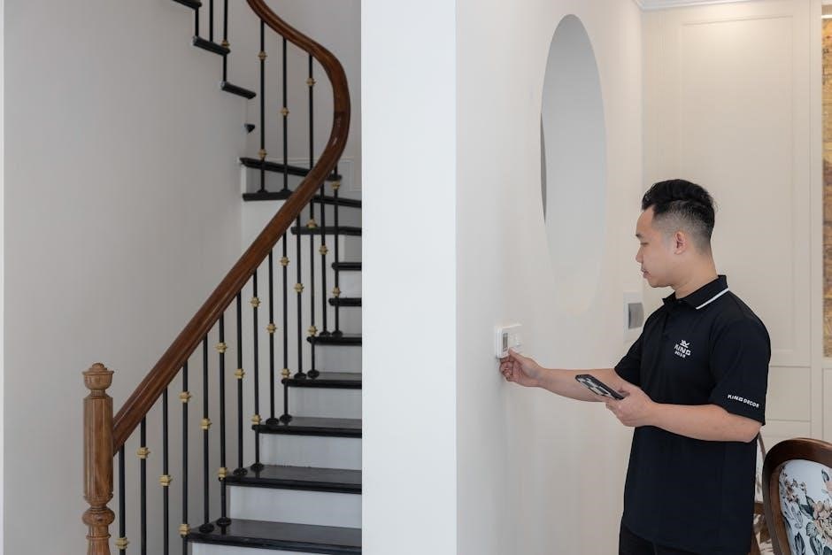
To navigate and configure your Viconics thermostat, accessing the main menu is the crucial first step. The process is straightforward, designed for ease of use during initial setup and ongoing adjustments. Begin by locating the MENU button on the thermostat’s faceplate; it’s typically a clearly labeled physical button.
Press and hold this MENU button for approximately ten seconds. A sustained press is required to bypass the standard operational display and enter the configuration mode. The display will change, indicating that you’ve successfully entered the menu. From here, you can adjust various settings, including branch number configuration, temperature calibration, and fan control parameters.
Be mindful that exiting the menu without saving changes will revert to the previous settings.
Branch Number Configuration
Once you’ve successfully accessed the main menu, the next step is configuring the branch number. This setting is vital for proper system identification and communication, especially in multi-zone setups. Utilize the UP and DOWN arrow buttons, conveniently located on the thermostat’s interface, to scroll through the available branch number options.
Each press of the UP or DOWN arrow will increment or decrement the displayed number, allowing you to pinpoint the correct branch assignment for this specific thermostat. Carefully review the system documentation or building plans to determine the appropriate branch number before proceeding.
Accuracy here ensures seamless integration and control within the overall HVAC system.
Confirming Branch Number Selection
After meticulously navigating to the desired branch number using the UP and DOWN arrow keys, it’s crucial to confirm your selection. This prevents accidental misconfiguration and ensures accurate system operation. To finalize the branch number assignment, simply press the ‘YES’ button on the thermostat.
Upon pressing ‘YES’, the thermostat will store the selected branch number in its memory and automatically return you to the main menu. A brief confirmation message may appear on the display, visually indicating successful configuration.
Double-check the displayed branch number on the main screen to verify its accuracy. You are now fully positioned within the system, ready for further configuration steps.
Programming & Control Sequences
Viconics VV550/551 controllers support Variable Air Volume (VAV) and single-duct digital control, accommodating diverse HVAC system needs and control sequences.
Variable Air Volume (VAV) Control
Viconics Tracer VV550 and VV551 controllers are specifically designed to provide robust Variable Air Volume (VAV) control for heating and cooling systems. These controllers excel in managing airflow to individual zones, optimizing thermal comfort and energy efficiency within a building. They dynamically adjust the volume of conditioned air supplied to each zone based on real-time demand, ensuring consistent temperatures and minimizing wasted energy.
The VAV control functionality allows for precise temperature regulation, responding quickly to changes in occupancy, solar load, or internal heat gains. This results in a more comfortable and productive indoor environment. Furthermore, the controllers support advanced control algorithms, enabling sophisticated strategies for optimizing VAV system performance and reducing operational costs. Proper configuration is key to maximizing the benefits of VAV control with Viconics systems.
Single-Duct Digital Control
Viconics VV550 and VV551 controllers offer comprehensive single-duct digital control capabilities, providing precise management of heating and cooling within a single ductwork system. This functionality allows for independent temperature regulation in various zones, enhancing comfort and optimizing energy usage. The digital control aspect ensures accurate and reliable operation, responding swiftly to changing conditions and user setpoints.
These controllers facilitate straightforward setup and operation for single-duct applications, simplifying building automation. They effectively manage dampers and other terminal units to deliver the appropriate amount of conditioned air to each zone. This results in a stable and comfortable indoor climate, while minimizing energy waste. The system’s digital precision ensures consistent performance and long-term reliability.
Supported Control Sequences
The Viconics Tracer VV550 and VV551 variable air volume (VAV) controllers are designed to support a diverse range of control sequences, enabling flexible adaptation to various HVAC system configurations. These sequences encompass standard heating and cooling operations, optimized for single-duct applications. The controllers effectively manage damper positions based on temperature feedback and setpoint adjustments, ensuring precise airflow control.
Supported sequences include proportional-integral-derivative (PID) control for stable temperature maintenance, and floating control for simpler applications. Furthermore, the controllers can accommodate economizer control strategies, leveraging outside air for free cooling when conditions permit. This adaptability allows for customized solutions tailored to specific building needs, maximizing efficiency and occupant comfort.
Advanced Features & Settings
Explore temperature calibration, setpoint adjustments, and comprehensive fan control settings within Viconics thermostats for optimized performance and tailored comfort preferences.
Temperature Calibration
Accurate temperature readings are crucial for efficient climate control. Viconics thermostats offer a temperature calibration feature, allowing users to fine-tune the displayed temperature to match a trusted external thermometer. This ensures the thermostat accurately reflects the ambient temperature, optimizing heating and cooling cycles.
To calibrate, navigate to the settings menu and locate the temperature calibration option. Follow the on-screen prompts to adjust the reading in small increments. Compare the thermostat’s display with a calibrated thermometer placed nearby. Repeat the adjustment process until the readings align. Proper calibration minimizes discrepancies and enhances overall system performance, leading to improved comfort and energy savings. Regularly checking and calibrating the temperature sensor is recommended for sustained accuracy.
Setpoint Adjustment
The setpoint defines the desired temperature the Viconics thermostat will maintain. Adjusting this setting allows users to personalize their comfort levels. Typically, setpoint adjustments are made directly through the thermostat’s interface using the up and down arrow buttons. The current setpoint is usually displayed prominently on the screen.
Users can establish separate setpoints for heating and cooling modes. Some models may offer scheduling features, enabling automated setpoint changes throughout the day to optimize energy usage. Consider factors like occupancy patterns and personal preferences when setting the desired temperature. Fine-tuning the setpoint ensures a comfortable environment while minimizing energy consumption. Regularly reviewing and adjusting setpoints can lead to significant cost savings.
Fan Control Settings
Viconics thermostats offer versatile fan control options to optimize air circulation and comfort. Users can typically select from modes like “Auto,” “On,” and potentially “Circulate.” In “Auto” mode, the fan operates only during heating or cooling cycles. Selecting “On” keeps the fan running continuously, providing consistent air mixing. The “Circulate” function periodically activates the fan to maintain even temperature distribution.
Advanced models may include adjustable fan speed settings, allowing for customized airflow. Proper fan control enhances comfort, reduces temperature stratification, and improves indoor air quality. Consider the building’s ventilation system and occupancy patterns when configuring fan settings. Experimenting with different modes can help identify the optimal balance between comfort and energy efficiency.
Troubleshooting Common Issues
This section addresses typical problems like power failures, inaccurate temperature readings, and communication errors, offering solutions for Viconics thermostat operation.
Thermostat Not Powering On
If your Viconics thermostat fails to power on, begin with the simplest checks. First, verify the power supply to the unit is active and within the specified voltage range. Inspect the wiring connections, ensuring they are secure and free from corrosion. A loose wire can easily interrupt the power flow.
Next, examine the circuit breaker or fuse associated with the thermostat’s power circuit; a tripped breaker or blown fuse will prevent operation. If the breaker trips repeatedly, there may be a short circuit requiring professional attention. Confirm the thermostat’s internal fuse (if applicable) hasn’t blown.
Finally, if the unit still doesn’t power on, consider a potential internal component failure and contact Viconics technical support for assistance. Do not attempt to disassemble the unit yourself, as this could void the warranty and pose a safety risk.
Incorrect Temperature Readings
If your Viconics thermostat displays inaccurate temperature readings, several factors could be at play. First, ensure the thermostat isn’t directly exposed to sunlight, drafts, or heat-generating appliances, as these can skew the sensor’s readings. Check for obstructions blocking airflow around the unit; proper ventilation is crucial for accurate sensing.
Utilize the Temperature Calibration feature within the thermostat’s menu to adjust the reading if a consistent offset exists. Compare the thermostat’s reading with a calibrated thermometer to determine the necessary adjustment. If calibration doesn’t resolve the issue, inspect the temperature sensor for damage or contamination.
A faulty sensor may require replacement. Contact Viconics technical support for guidance on sensor replacement or further troubleshooting steps. Remember to allow sufficient time for the thermostat to stabilize after installation or adjustments.
Communication Errors
Experiencing communication errors with your Viconics thermostat often indicates a problem with the connection to a Building Management System (BMS) or other connected devices. First, verify all wiring connections are secure and correctly implemented according to the installation guide. Ensure the communication protocol settings (e.g., BACnet, Modbus) are correctly configured on both the thermostat and the BMS.
Check for any physical obstructions or interference affecting the communication signal. If using a wireless connection, confirm sufficient signal strength and minimal interference from other devices. A reset of the thermostat’s communication module might resolve temporary glitches.
If the issue persists, consult the BMS documentation or contact Viconics technical support for assistance with troubleshooting communication protocols and network configurations.
Load Calculation & System Integration
This section provides forms for calculating heating/cooling loads and details integrating Viconics thermostats with Building Management Systems (BMS) for optimal control.
Heating & Cooling Load Calculation Forms
Accurate load calculations are crucial for proper system design and efficient thermostat operation. Viconics provides comprehensive forms to assist engineers and installers in determining the heating and cooling demands of a building. These forms systematically gather essential project information, including building dimensions, construction materials, insulation values, window specifications, and occupancy levels.
The forms are structured to account for various heat gain and heat loss factors, such as solar radiation, internal heat generation from equipment and occupants, and ventilation requirements. Detailed sections cover walls, roofs, floors, windows, and doors, allowing for precise input of thermal properties. Properly completed forms ensure the selected Viconics thermostat model and control strategy are appropriately sized and configured for the specific application, maximizing comfort and energy savings.
Project Information Input
The initial stage of heating and cooling load calculation involves meticulous project information input. This section of the Viconics load calculation form requires detailed data about the building’s location, including city and state, to determine design temperatures. Accurate building dimensions – length, width, and height – are essential, alongside a comprehensive description of the building’s construction type and usage.
Further input includes details on wall, roof, and floor construction, specifying materials and insulation R-values. Window and door specifications, such as glazing type and area, are also critical. Finally, information regarding occupancy levels, internal heat gains from equipment, and ventilation rates completes the project profile. Precise data entry here directly impacts the accuracy of the subsequent load calculations.
Integrating with Building Management Systems (BMS)
Viconics thermostats, particularly the VV550 and VV551 controllers, are designed for seamless integration with modern Building Management Systems (BMS). This connectivity enables centralized monitoring and control of HVAC systems, optimizing energy efficiency and occupant comfort. Communication protocols commonly supported include BACnet and potentially others, allowing for data exchange regarding temperature, setpoints, and operational status.
Successful BMS integration requires proper configuration of communication parameters within both the Viconics thermostat and the BMS platform. This includes assigning unique device addresses and mapping data points. Utilizing a robust network infrastructure is crucial for reliable communication; Integration allows for advanced features like scheduling, alarming, and trend logging, enhancing overall building performance.

Maintenance & Safety
Regular cleaning with a dry cloth ensures optimal performance. Always disconnect power before maintenance and adhere to standard electrical safety precautions during operation.
Cleaning Procedures
To maintain the longevity and accuracy of your Viconics thermostat, regular cleaning is recommended. Always disconnect the power supply to the thermostat at the breaker before commencing any cleaning procedures. This is a crucial safety precaution to prevent electrical shock or damage to the unit.
Use a soft, dry cloth to gently wipe the exterior surfaces of the thermostat. Avoid using abrasive cleaners, solvents, or excessive moisture, as these can damage the display or internal components. For stubborn dirt or grime, lightly dampen the cloth with water, ensuring it is wrung out thoroughly to prevent water ingress.
Pay particular attention to cleaning the display screen, using gentle circular motions. Do not apply direct pressure to the screen. Avoid spraying any liquids directly onto the thermostat; instead, apply to the cloth first. Regular dusting will also help prevent buildup and maintain a clean appearance.
Safety Precautions
Important: Disconnect power at the breaker before installation, maintenance, or cleaning. Working with electrical systems presents inherent risks; improper handling can lead to serious injury or property damage. Only qualified personnel should perform installation and complex troubleshooting.
Ensure all wiring connections are secure and comply with local electrical codes. Do not expose the thermostat to excessive moisture, extreme temperatures, or direct sunlight. Avoid dropping or subjecting the unit to physical shock.
Never attempt to disassemble or repair the thermostat beyond the procedures outlined in this manual. Unauthorized modifications will void the warranty and may compromise safety. If the unit exhibits signs of damage, discontinue use immediately and contact technical support. Always prioritize safety when interacting with electrical equipment.
Warranty Information
Viconics thermostats are warranted against defects in materials and workmanship for a period of one year from the date of original purchase. This warranty covers repair or replacement of the defective unit, at Viconics’ discretion. Damage resulting from improper installation, misuse, abuse, or unauthorized modifications is not covered.
To initiate a warranty claim, contact Viconics Technical Support with proof of purchase and a detailed description of the issue. Returned units must be shipped prepaid to a designated Viconics service center.
This warranty is extended only to the original purchaser and is non-transferable. Viconics disclaims all other warranties, expressed or implied, including any implied warranty of merchantability or fitness for a particular purpose.

Resources & Support
For comprehensive assistance, visit the Viconics official website or directly contact their technical support team for expert guidance and troubleshooting.
Viconics Official Website
The Viconics official website serves as a central hub for all product-related information, documentation, and support resources. Users can access detailed specifications for each thermostat model, including the VV550 and VV551 controllers, alongside comprehensive manuals covering initial setup, configuration, and advanced programming techniques.
Furthermore, the website provides access to load calculation forms essential for proper system integration and ensures optimal performance. It also features a dedicated section for frequently asked questions (FAQs) addressing common troubleshooting issues, such as power-on failures or inaccurate temperature readings.
Visitors can find information regarding warranty details and safety precautions, ensuring responsible operation. The site also lists contact information for direct technical support, facilitating prompt assistance with any inquiries or challenges encountered during installation or usage.
Technical Support Contact Information
For dedicated assistance with Viconics thermostats, including the VV550 and VV551 series, and to resolve issues related to configuration, programming, or system integration, several support channels are available. While direct contact details aren’t explicitly provided in the source material, Viconics typically offers support through their parent company or authorized distributors.
Users are encouraged to first consult the comprehensive documentation available on the official Viconics website, which addresses common troubleshooting scenarios like power failures or temperature inaccuracies. If further assistance is needed, contacting Dwyer Instruments, a related brand, may yield helpful resources.
Alternatively, reaching out to a local HVAC professional familiar with Viconics products is recommended for on-site support and expert guidance. Always have your model number ready when contacting support.